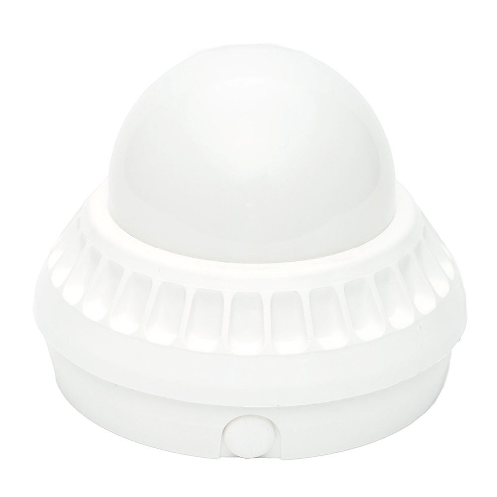
Construction:
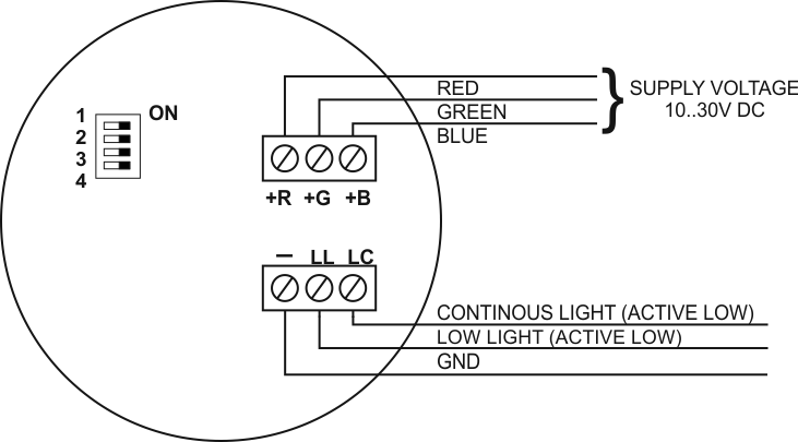
SO-Ad2 optical alarm device has got the casing made of non-flammable plastic material, in which there are electronic components. In the top part of the casing there is the light source – LED RGB diode. Signalling devices of SO-Ad2 series have got in their cover: a supply terminal, a control terminal as well as a four-level microswitch, by means of which it is possible to choose duty cycle as well as frequency of signaling device flashes.
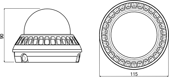
The additional element of the casing is the socket enabling to direct mounting of the signaling device to the ceiling or wall by means of two screws and wall plugs. SO-Ad2 is an optical alarm device, which enables optical signal generation of seven colours. The colour of generated signal is dependent on the supply input state of the signaling device. According to the principle of mixing colours R, G, B, through appropriate control of inputs the user receives colours consistent.
The signalling device is activated through connecting the supply voltage to supply inputs controlling the colour components. The optical signal received in this method is ”mixed” digitally in order to receive appropriate colour proportions, what causes receiving the clear colour. Depending on the number of active inputs, the user receives the colour of warning signal consistent with the table below.
| Supply input | Signal colour | ||
| +R | +G | +B | |
| +Uz | NC | NC | Red |
| NC | +Uz | NC | Green |
| NC | NC | +Uz | Blue |
| +Uz | +Uz | NC | Yellow |
| NC | +Uz | +Uz | Light blue |
| +Uz | NC | +Uz | Purple |
| +UZ | +Uz | +Uz | White |
NC – unconnected; +Uz – supply voltage
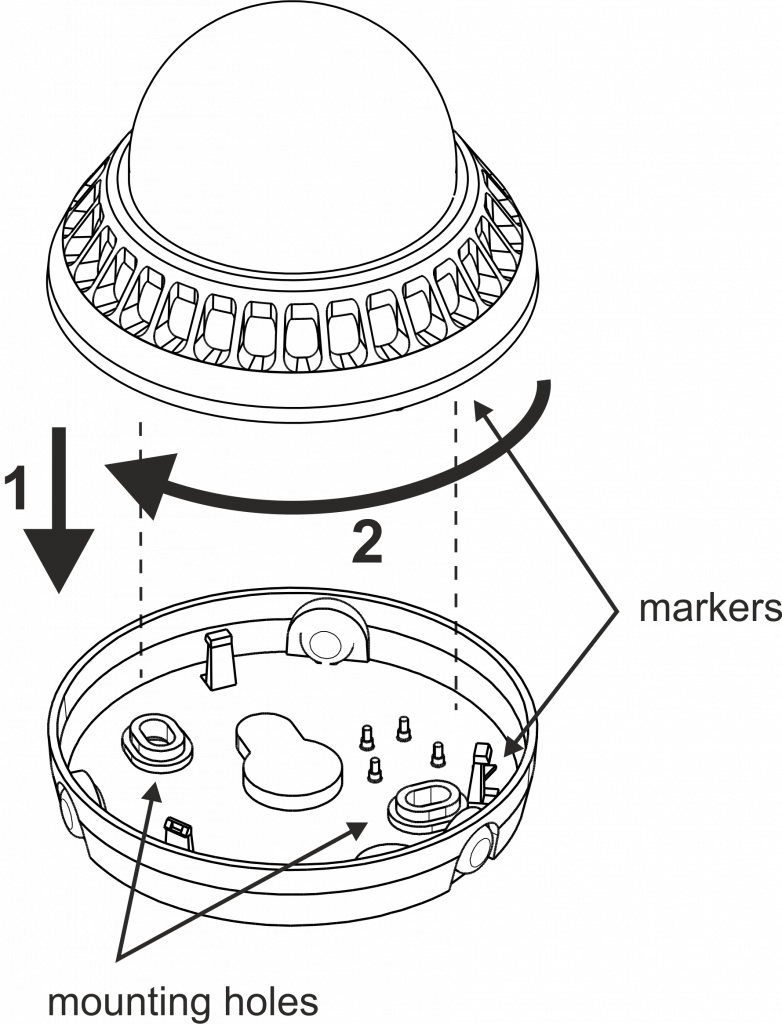
Opening:
To open the signalling device: screw out the screw locking the base, turn the shade anticlockwise while holding the base, then separate the shade and the base.
Closing:
To close the signalling device: fit together the markers. After that put together the device and turn in the direction marked with an arrow (the sequence in the drawing). On closing, lock the base by screwing in the locking screw.