CONTROL DESCRIPTION
The KS-Ad signal column through the built-in control system enables generating optical as well as acoustic and optical signals such as:
- fixed light,
- pulsed light 1 Hz, flash time of 0.5 s,
- pulsed light 5 Hz,
- rotating light for all colours except for green,
- irregular light (irregular flash frequency) for all colours except for green (except for the colour 3 counting from the top)
- brightness modulation, only for the green colour,
- in the version without a sound module, the strobe light for the red signal.
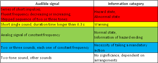
| OPTICAL SIGNAL |
ACOUSTIC SIGNAL |
|
Increased frequency from 400 Hz to 1300 Hz during 1s (microswitch SIGNAL/STR in the position “0”), increased frequency from 2400 Hz to 2850 Hz during 0.14 s (microswitch SIGNAL/STR in the position “1”) |
|
Frequency 2850 Hz: serially 60 ms of sound, 120 ms of silence |
|
Constant sound 300 Hz |
|
Serially selections of 0.5 s with the frequency of 800 Hz, 700 Hz |
|
Frequency 3000 Hz, 3 bundles of pulses with the time duration of 32 ms each one (sound and silence of 16 ms) separated with the silence of 0.5 s, and then 1.5 s of silence |
Acoustic signal combination
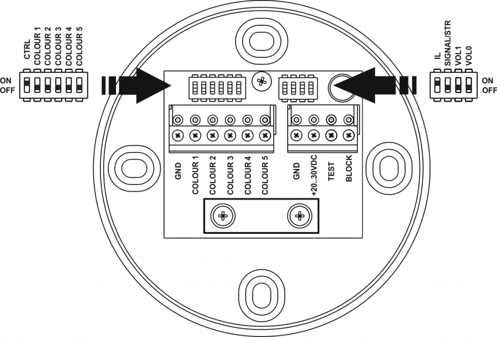
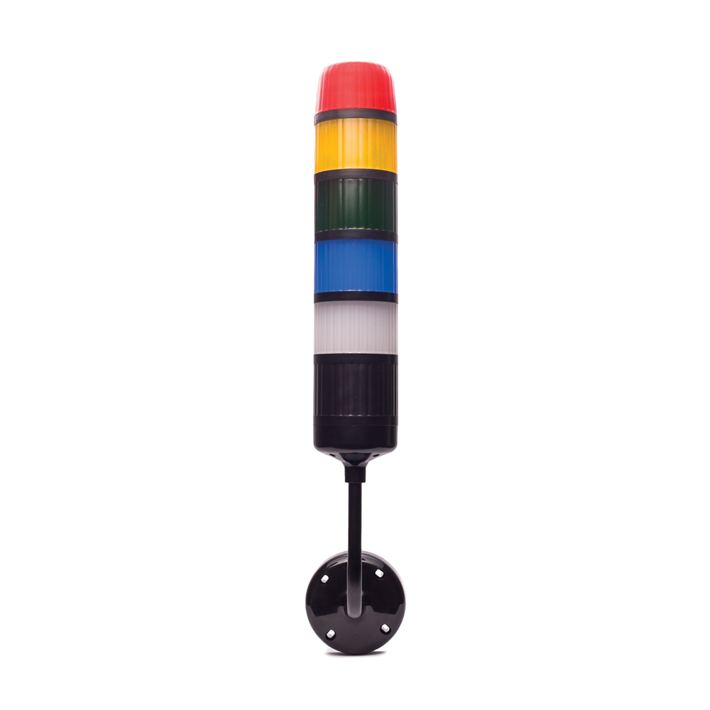
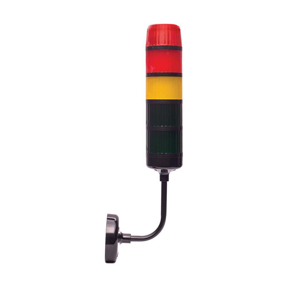
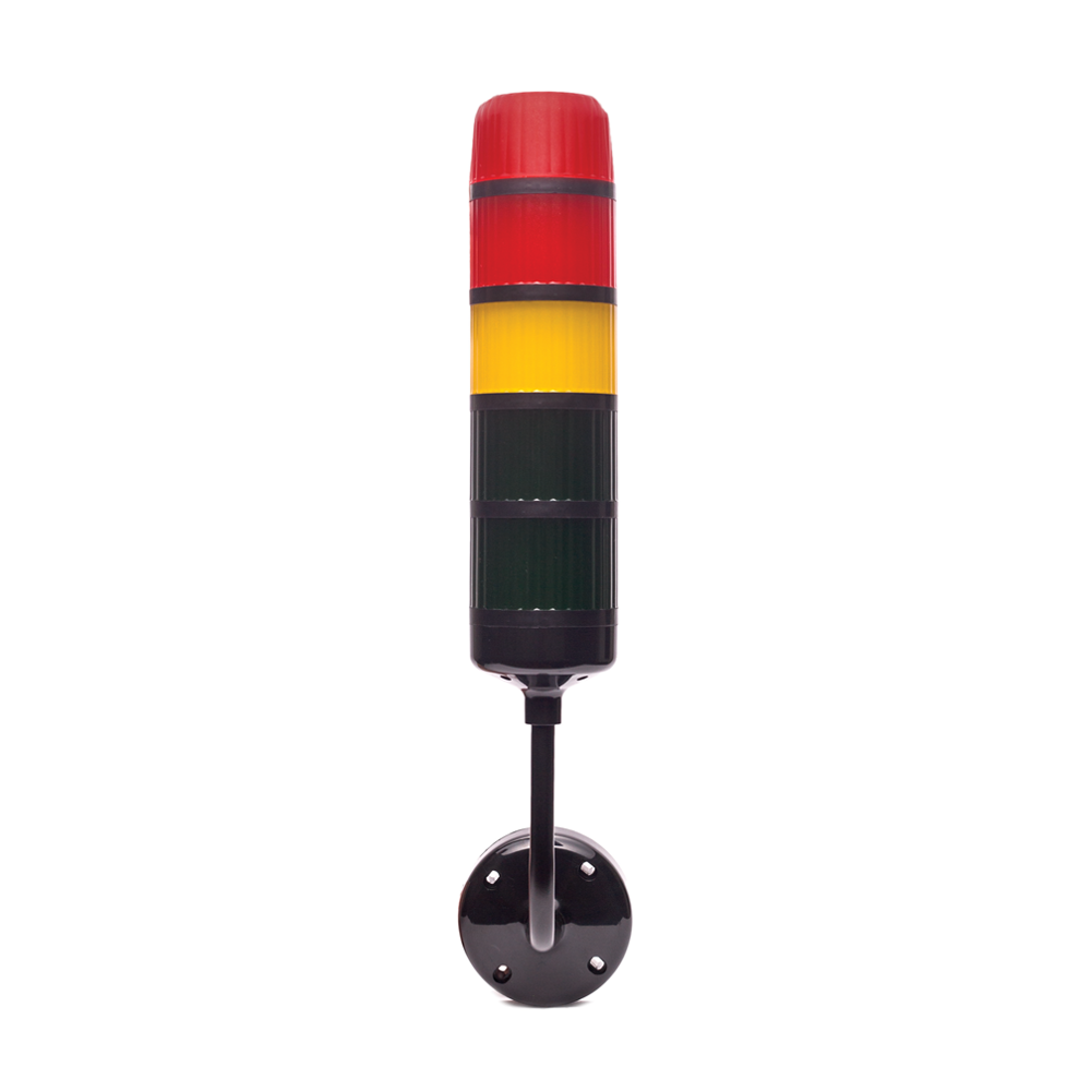
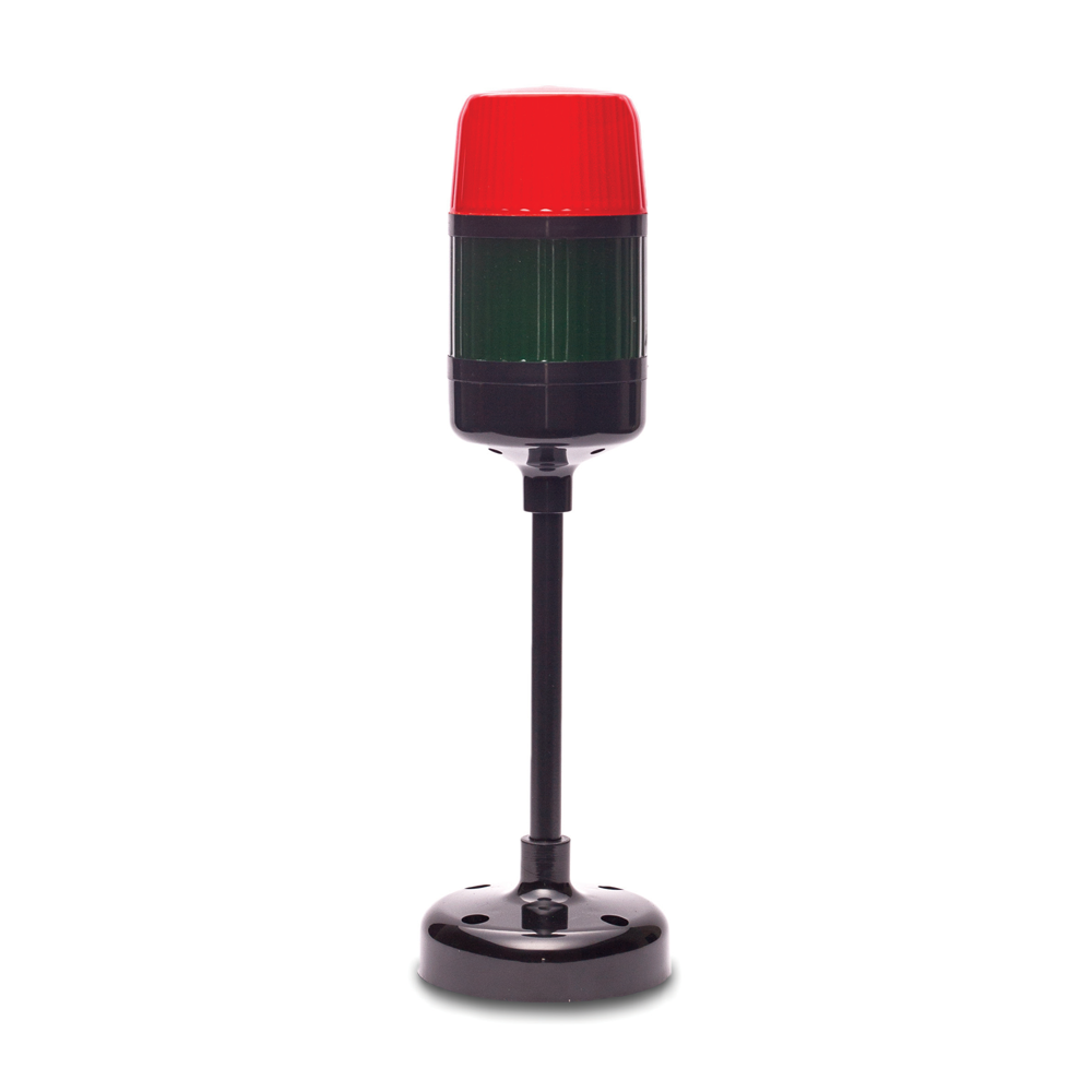
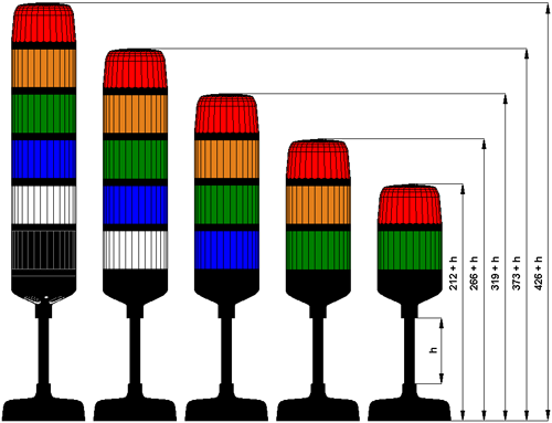
Control element layout in the KS-Ad signal tower
SIGNALS CONTROLLING OPERATION OF THE KS-Ad COLUMN
The KS-Ad tower has got the number of inputs dependent on the number of colours as well as the presence of sound module.
COLOUR 1 controlling input for the red colour (or the first counting from the top of the tower),
COLOUR 2 controlling input for the yellow colour
COLOUR 3 controlling input for the green colour
COLOUR 4 controlling input for the blue colour
COLOUR 5 controlling input for the white colour
TEST test input (giving the ground introduces the tower into the testing mode),
BLOCK input of acoustic signal lockout (when connected to gnd, acoustic signal is locked out),
VCC supply voltage input +20..30 V DC,
GND double input of supply voltage ground.
The signal tower has also got microswitches installed in the basis, which have the following functions:
COLOUR 1…COLOUR 5 selection of the input configuration,
CTRL selection of the controlling type for inputs: analogue, volt-free or digital,
IL selection of the option ”Irregular light” – the option of irregular light,
SIGNAL/STR selection of sound type for the red light, additional optical signal (version without an acoustic module),
VOL 1 – selection of volume degree (four-level control),
VOL 0 – selection of volume degree (four-level control).
METHODS OF CONTROLLING THE KS-Ad SIGNAL TOWER OPERATION
The KS-Ad signal tower offers the user three controlling options: analogue (voltage or resistance dialled by means of microswitches COLOUR 1..COLOUR 5), volt-free (binary control by means of relay contacts) as well as digital control (two-stage). The selection of control type is made by means of the microswitch CTRL placed in the device basis.
In case of analogue control each tower input (COLOUR 1..COLOUR 5) can be controlled independently (e.g. 4 inputs in the voltage way, 1 input in the resistance way). In the voltage mode the voltage given on terminals should be included in the range of 0..10 V DC.
In the volt-free control mode all inputs operate in the two-stage mode: input connected to gnd or left unconnected. The change of control input state can be made e.g. by means of relay contacts.
In case of digital control the user gives signals of two logical levels to the tower input. This controlling is as good as it can be connected with the free-volt control, i.e. some inputs can be controlled in a free-volt way and others – in a digital way.
The control system of the signal tower prevents generating accidental warning signals as a result of incorrect control. In case of appearing a fault (or breakdown) in the system applying control signals to the tower input (e.g. a situation, when the user wants to receive two acoustic signals at the same time) the tower electronic system operates on a priority basis (reproduces the signal of greater importance). It means that e.g. when there is a warning signal and then there appears the danger signal, the tower will reproduce the danger signal.
Additionally, the KS-Ad signal tower has got: the option of switching off the audible signal, a test mode, the option IL (Irregular light), the possibility of selecting the additional sound for the red light as well as in case of the version without an acoustic mode the option of selecting the strobe light for the red colour.
Switching off an audible sound:
When it’s necessary to switch off an acoustic signal quickly the user has the acoustic signal blockade “BLOCK” input at his disposal. Connecting gnd to this input causes immediate switching off the acoustic signal regardless of the input state COLOUR 1..COLOUR 5, whereas in the analogue control mode it’s enough to short connect to gnd, however in case of free-volt as well as digital control it must be a stable state until the moment of appearing the next control signal.
CAUTION!
In the analogue mode generating a new (different) acoustic and optical signal eliminates a sound blockade.
Test mode:
This mode is designed for checking operation of the signal tower optical and acoustic systems. Entering the test mode takes place through connecting the supply gnd to the input: ”TEST”, it causes generating the fixed light of all tower colours as well as simultaneous sound generation with the constant frequency (300 Hz). The sound can be switched off by the input of acoustic signal blockade.
CAUTION!
During the test the tower does not react to the input state COLOUR1…COLOUR5.
Option IL:
In case of switching on the option of irregular light (microswitch IL placed in the device basis) the rotary light effect is replaced with the irregular light, thanks to which it is more perceptible as a human being is not able to get used to the changing signal.
Selection of the additional sound for the red light:
There is possibility of selecting one out of two acoustic signals available for the red light by means of the microswitch SIGNAL placed in the device basis.
SIGNAL put in the position 0: serially increased frequency from 400 Hz to 1300 Hz during 1 s,
SIGNAL put in the position 1: serially increased frequency from 2400 Hz to 2850 Hz during 0.14 s.
Selection of the strobe light for the red colour (only in the version without an acoustic module):
There is possibility of selecting the additional optical effect for the red colour, by means of the microswitch SIGNAL/STR. In case of switching over the microswitch in the position ”ON”, there is chosen the strobe light type. This light is active only for the red colour (or the first colour counting from the top of the tower, in case of nonstandard product).
1. Analogue voltage control:
This tower control mode is selected by means of the microswitch CTRL put in the position ”ON”, the microswitch COLOUR 1..COLOUR 5 in the position ”OFF”.
In case of voltage control the user applies the voltage signal in the range of 0-10 V DC to terminals of the tower COLOUR 1..COLOUR 5. Depending on the level of the control signal the tower generates appropriate optical as well as audible signals.
| Voltage on the signal tower input V DC |
Effect |
| 0 |
No reaction |
| 1.5 ±0.3 V |
Sound |
| 2.5 ±0.3 V |
Fixed light, no sound |
| 3.5 ±0.3 V |
Fixed light + sound |
| 4.5 ±0.3 V |
Pulsed light 1 Hz, no sound |
| 5.5 ±0.3 V |
Pulsed light 1 Hz + sound |
| 6.5 ±0.3 V |
Pulsed light 5 Hz, no sound |
| 7.5 ±0.3 V |
Pulsed light 5 Hz + sound |
| 8.5 ±0.3 V |
Rotary light without sound |
| 9.5 ±0.3 V |
Rotary light + sound (or irregular light in case of choosing this option, additionally in the version without an acoustic module – the possibility of choosing the strobe light for the red colour) |
| CAUTION!
In case of the green colour, the rotary light is replaced with the effect of light intensity modulation. |
Table 1.1. Voltage signal values in the analogue voltage control
2. Analogue resistance control
This tower control mode is selected by means of the microswitch CTRL put in the position ”ON”, the microswitch COLOUR 1 ..COLOUR 5 in the position ”ON”.
In case of resistance control the user connects the given resistance value to terminals of the tower COLOUR 1..COLOUR 5. Depending on this value the tower generates appropriate optical as well as audible signals.
| Value of the resistance connected to the signal tower input |
Effect |
| 0 Ω or resistance not connected |
No reaction |
| 470 Ω ±5% |
Sound |
| 910 Ω ±5% |
Fixed light, no sound |
| 1.5 kΩ ±5% |
Fixed light + sound |
| 2.2 kΩ ±5% |
Pulsed light 1 Hz, no sound |
| 3 kΩ ±5% |
Pulsed light 1 Hz + sound |
| 4.3 kΩ ±5% |
Pulsed light 5 Hz, no sound |
| 6.2 kΩ ±5% |
Pulsed light 5 Hz + sound |
| 10 kΩ ±5% |
Rotary light without sound |
| 15 kΩ ±5% |
Rotary light + sound (or irregular light in case of choosing this option, additionally in the version without an acoustic module – the possibility of choosing the strobe light for the red colour) |
| CAUTION!
In case of the green light (or colour 3 counting from the top) the rotary light is replaced with the effect of light intensity modulation. |
Table 2.1. Resistance values in the analogue resistance control
3. Free-volt control
This tower control mode is selected by means of the microswitch CTRL put in the position ”OFF”, microswitches COLOUR 1..COLOUR 5 in the position ”ON”. In this mode tower inputs operate in the free-volt way. Inputs are shorted to ground or they are left unplugged. This control type can be done e.g. by means of relay contacts.
In the free-volt control the compact input to ground means the fixed light generation for the appropriate colour. If it is necessary to generate the pulsed light, the user self-controls the contact, shorting the input to ground in a pulsed way. In case of restricted sequences (e.g. red and green colours simultaneously) the device generates the luminous effect consistent with the table below.
| Colour 1 |
Colour 2 |
Colour 3 |
Colour4 |
Colour5 |
Effect |
| R |
Z |
Z |
X |
X |
Rotary light with sound for the red COLOUR (or irregular light), for the white as well as blue COLOUR the presence of optical signal is dependent on the state of inputs COLOUR4, COLOUR5. |
| Z |
R |
Z |
X |
X |
Rotary light with sound for the yellow COLOUR (or irregular light), for the white as well as blue COLOUR the presence of optical signal is dependent on the state of inputs COLOUR4, COLOUR5. |
| Z |
Z |
R |
X |
X |
Light intensity modulation with sound for the green COLOUR, for the white as well as blue COLOUR the presence of optical signal is dependent on the state of inputs COLOUR4, COLOUR5. |
| Z |
Z |
Z |
Z |
R |
Rotary light with sound for the blue COLOUR (or irregular light). |
| Z |
Z |
Z |
R |
Z |
Rotary light with sound for the white COLOUR (or irregular light). |
| Z |
Z |
Z |
Z |
Z |
ALL COLOURs with rotary light and gradient for the green colour, without sound |
| Z |
Z |
Z |
R |
R |
Demo effect without sound |
Table 3.1. Combinations in the free-volt control
Legend:
Z input connected to ground,
R input left unconnected,
X optional input state (Z or R).
4. Digital control
This tower control mode is selected by means of the microswitch CTRL put in the position ”OFF”, microswitches COLOUR 1..COLOUR 5 in the position ”OFF”. In this mode the user applies two voltage levels (logical) to tower inputs. The level ”0” of the logical one corresponds with the voltage 6..10 V, the level ”1” of the logical one – the voltage of 0..2 V DC.
The application to terminals of the logical tower ”1” causes the fixed light generation for the appropriate COLOUR.
In case of restricted sequences the system generates effects consistent with the Table 3.1., whereas:
Z Logical “1” on tower input
R Logical “0” on tower input
X optional logical state in the input.
CAUTION!!!
Exemplary control circuit diagrams are in the bookmark “Download”.