SO-P8 VISUAL ALARM DEVICE HOLDS DOCUMENTS ISSUED BY CNBOP-PIB:
- CERTIFICATE CPR NO. 1438-CPR-0875
- CERTIFICATE OF APPROVAL NO. 4826/2023
ATTENTION! Documents to be downloaded after logging in to the Client Zone
Use:
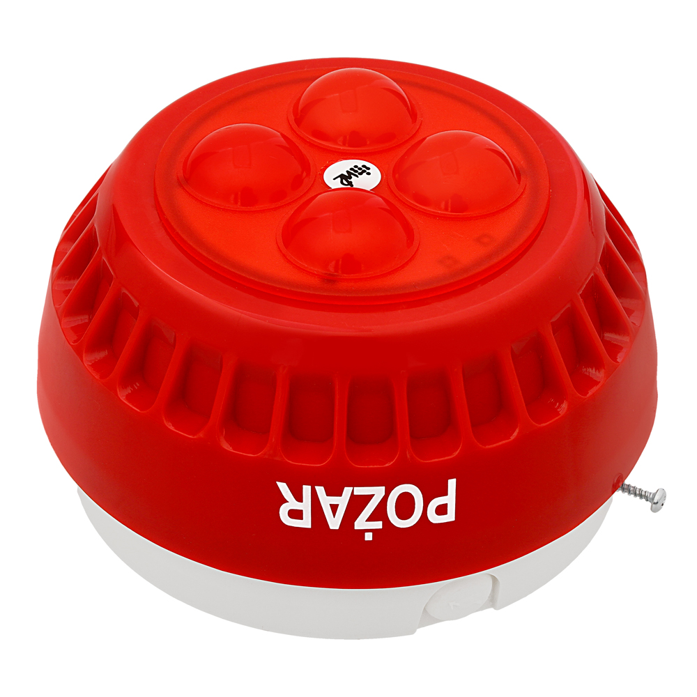
The SO-P8 visual alarm device is intended for signalling of fire inside and outside buildings.
Construction:
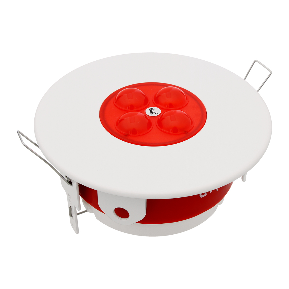
The visual alarm device has a housing made of non-flammable material, in which electronic components are located. The housing consists of three parts: a body with a mounted LED lamp, a cover with a mounted printed circuit board, a base for mounting to the wall/ceiling or directly to the PIP-1AN or PIP-3AN box.
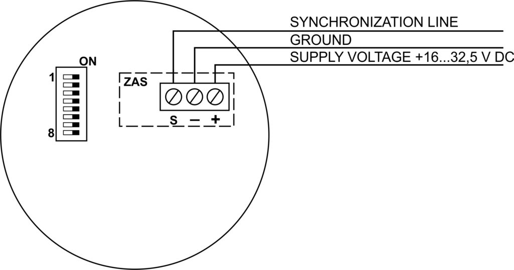
The lid contains:
- power connector,
- eight-position microswitch.
The power connector has three pins marked “+”, “-“, and “S”. The “+” and “-” terminals are used for power supply, while the “S” terminal is used for connecting an additional synchronization wire.
Using a microswitch, it is possible to select the operating mode of the VAD – “master” or “slave”, select the delay time, select the frequency of flashes or select the solid coverage area (3m, 6m, 9m, 12m).
Operating design:
After connecting the power supply, the SO-P8 visual alarm device generates an optical pulse signal with a flash time shorter than 0.2 s. By default, the frequency of the generated optical signal is 0.5 Hz. The light-generating element is LED diodes, placed in a housing (diffuser) forming an optical part. SO-P8 enables the creation of a network of signaling devices operating synchronously (synchronized optical part).
Varieties:
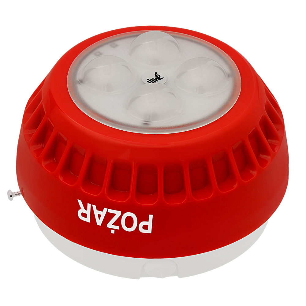
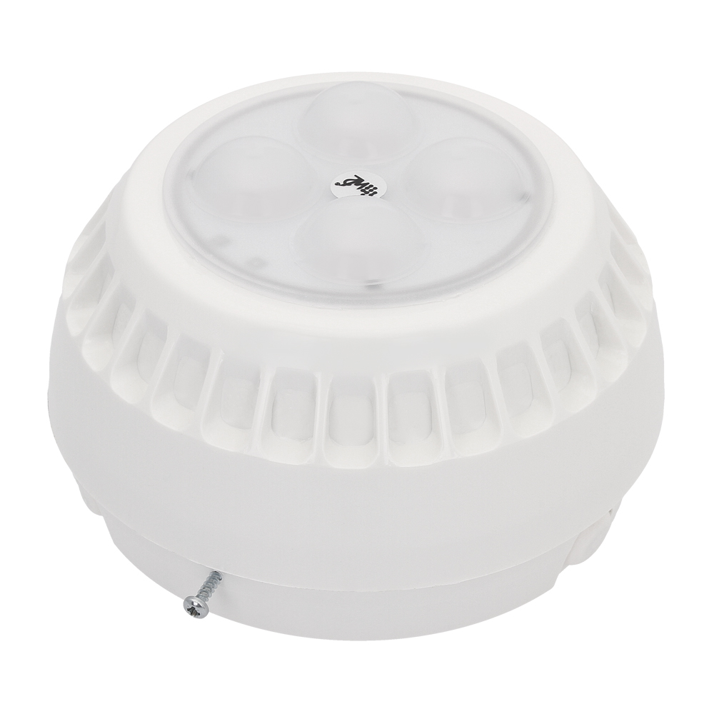
The SO-P8 VAD is available in 6 varieties.
| Varieties |
Description |
| SO-P8/CC |
VAD in red housing, red light |
| SO-P8/CB |
VAD in red housing, white light |
| SO-P8/CM |
VAD in red housing, alternating red and white light |
| SO-P8/BC |
VAD in white housing, red light |
| SO-P8/BB |
VAD in white housing, white light |
| SO-P8/BM |
VAD in white housing, alternating red and white light |
NOTICE!
Certificate of Admittance is only valid in Poland for SO-P8/CC variety.
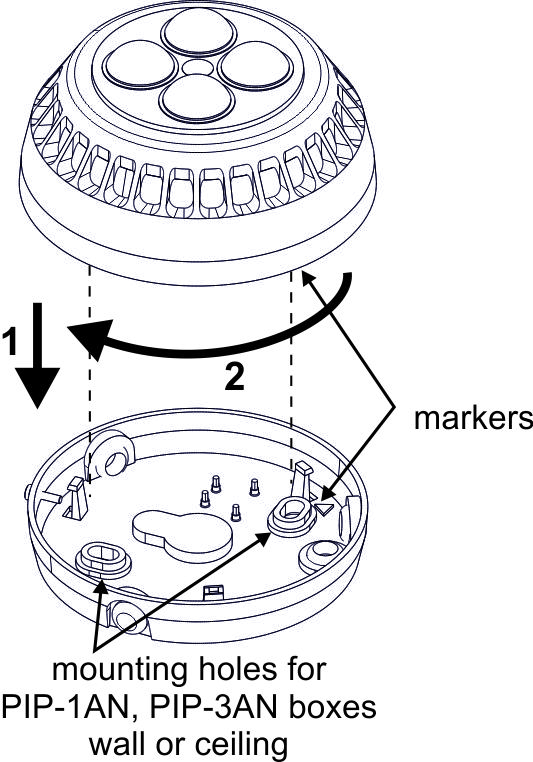
Opening:
To open the alarm device you should: screw out the blocking screw, twist the shade to the left while holding the base, then move apart the shade and the base.
Closing:
To close the alarm device adjust the markers, then assemble the device and twist it to the direction marked with an arrow (sequence shown in the drawing). After closing, screw in the blocking screw.
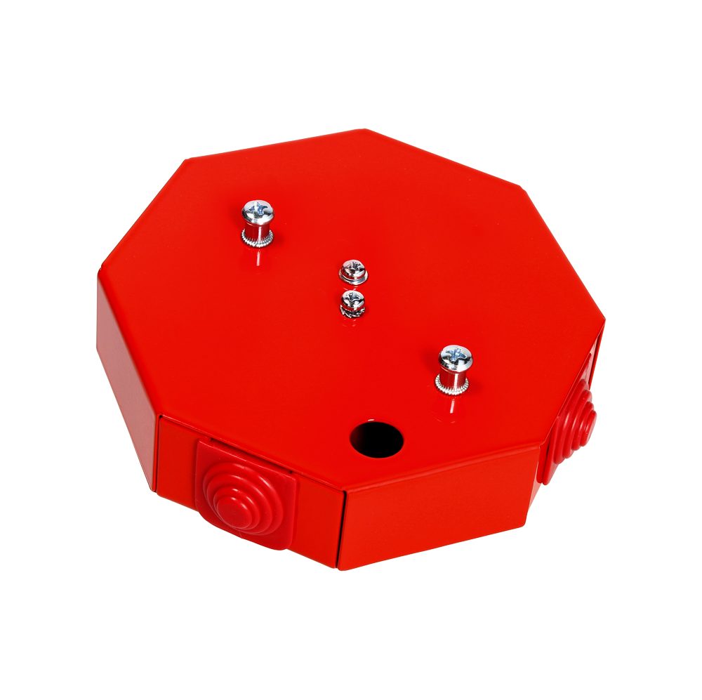
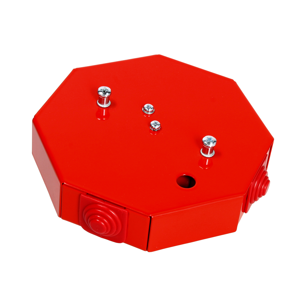
Assembly recommendations:
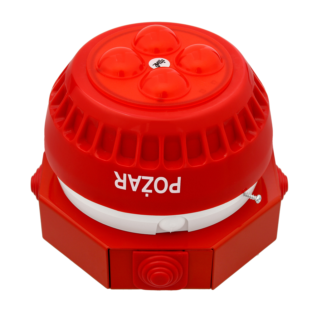
The SO-P8 VADs should be connected to the FAS installation through junction boxes with the required class of maintaining electrical functions (recommended PIP-3AN/0.75A). If there is no need to use the synchronization option of the SO-P8 VADs, it is also possible to mount them through the PIP-1AN/0.375A installation box, observing the following information on the mounting method. If mounting directly on the box is not required, the PIP-2AN/0.375A box can be used to connect the device.
The box should be mounted to the substrate/wall with the required fire resistance. If, for aesthetic reasons, it is not possible to mount the signaling device directly on the PIP box, it is permissible to mount the signaling device to the base that does not have the required fire resistance, while the PIP junction box must be mounted on the base with the required fire resistance (e.g. a situation in which the box PIP is mounted to the ceiling with E90 resistance, while the SO-P8 signaling device is mounted in the suspended ceiling). Detailed guidelines for the installation of PIP installation boxes are included in the National Technical Assessment CNBOP-PIB-KOT-2019/2024/0113-3704 wydanie 1.
The mounting cover OM-2 is intended for installation in a suspended ceiling. This procedure allows the device to be hidden in the suspended ceiling, which increases the aesthetic value of the installation.
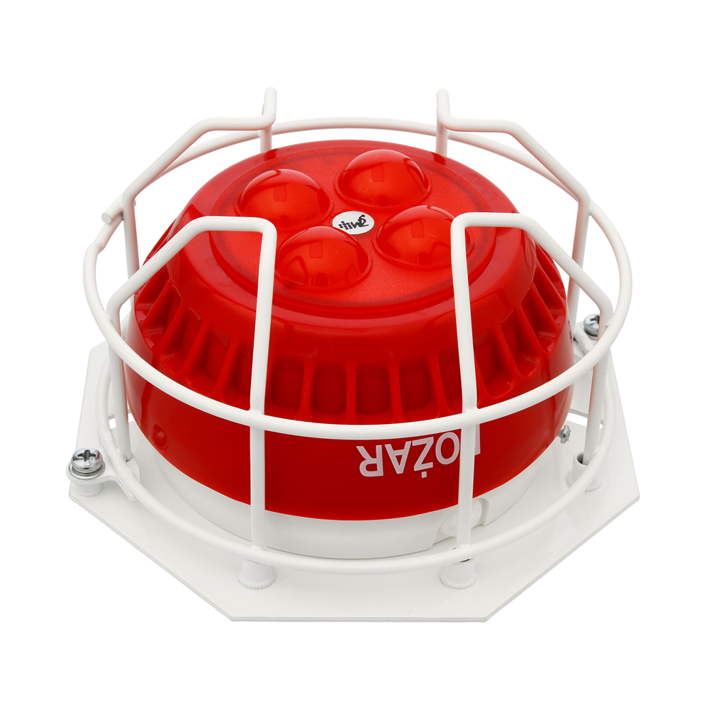
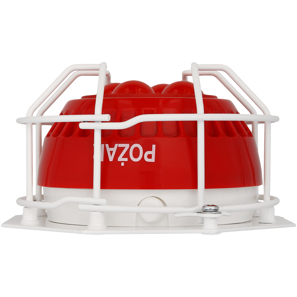
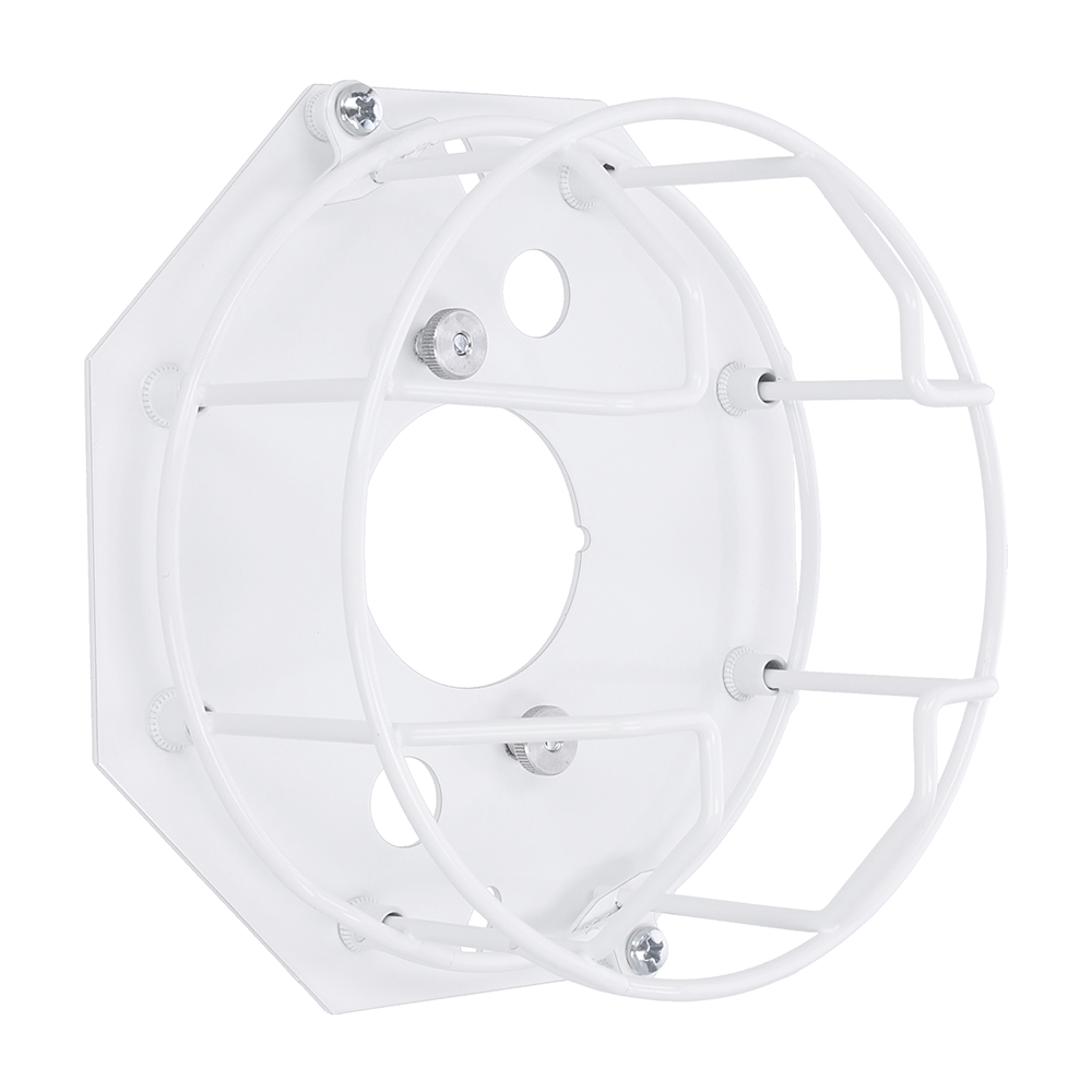
If there is a need to protect the signaling device against mechanical damage at the installation site, the OZ-50-2 protective cover can be used.
| Type |
visual alarm device |
| Supply voltage |
16-32,5 V DC |
| Current consumption in off state |
0 mA |
| Current consumption in on state |
<30 mA* |
| Power consumption in on state |
<0,72 W* |
| Sound output |
not applicable |
| Flash frequency |
0,5 Hz* |
| Flash time |
~150 ms* |
| Time between flashes |
~1850 ms* |
| Device category |
O |
| Device type |
type B |
| Working temperature |
from -25°C to +70°C |
| IP protection degree |
IP54 |
| IK protection degree |
IK07 |
| Conductor cross-section |
2,5 mm2 |
| Dimensions |
Ø114×70 mm |
| Weight |
~230 g |
*for default settings and supply voltage Uz=24 V DC, optical shape 3m, flash frequency 0,5 Hz, delay time 0 s)
Control:
Connecting the supply voltage to the appropriate terminals triggers the flashing signal.
| Number of microswitch |
Mark |
Function |
| 1 |
M/S |
Operating mode selection MASTER (ON) / SLAVE (OFF) |
| 2 |
D0 |
Delay time selection |
| 3 |
D1 |
Delay time selection |
| 4 |
D2 |
Delay time selection |
| 5 |
F0 |
Flash frequency selection |
| 6 |
F1 |
Flash frequency selection |
| 7 |
L0 |
Optical shape selection |
| 8 |
L1 |
Optical shape selection |
Control – devices network:
SO-P8 VADs can work in a network. Devices that are to be synchronized with each other should be connected with an additional conductor marked as S. Only one device in the network should be set as MASTER, the rest as SLAVE. The figure below shows an example of a SO-P8 synchronization scheme.
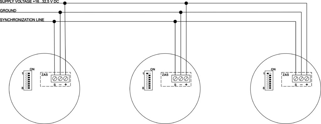
NOTICE! SO-P8 devices can also be synchronized with other signaling devices produced by W2:
- SA-K7N – optical part
- SAOZ-Pk2 – optical part
- SAO-P8 – optical part
For correct synchronization, the SO-P8 VADs must flash with a frequency of 0.5 Hz.
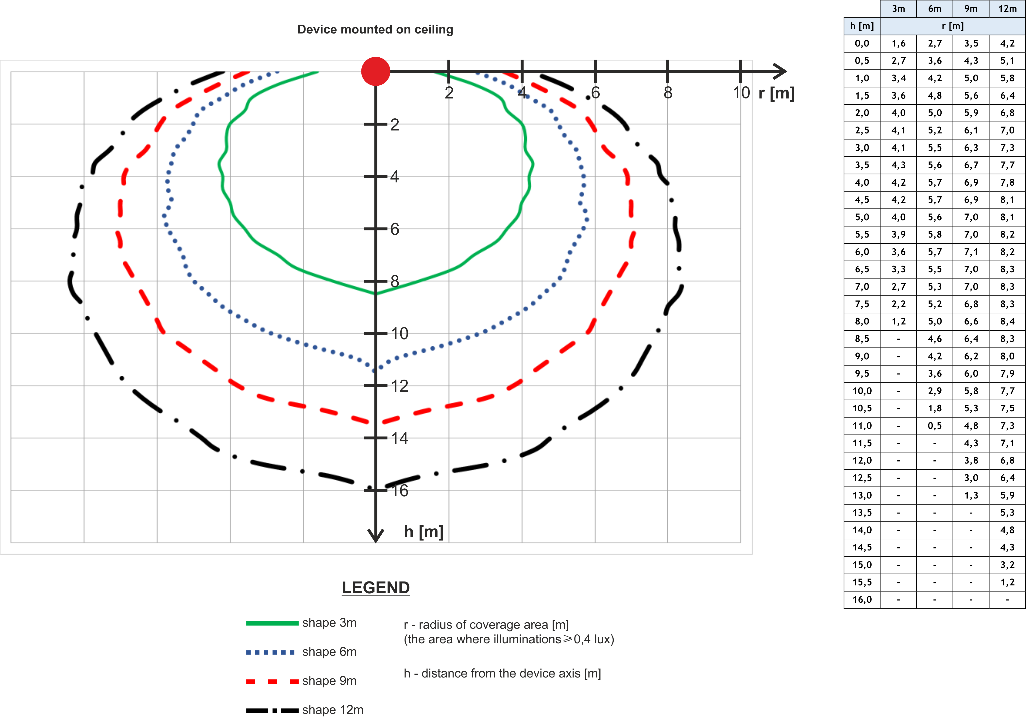
Ceiling mounting – red light:
The diagram for the installation of SO-P8 VAD (varieties with red light) on the ceiling is presented below. The table opposite shows the radius of the coverage area depending on the installation height (h) and selected optical shape.
Click to enlarge
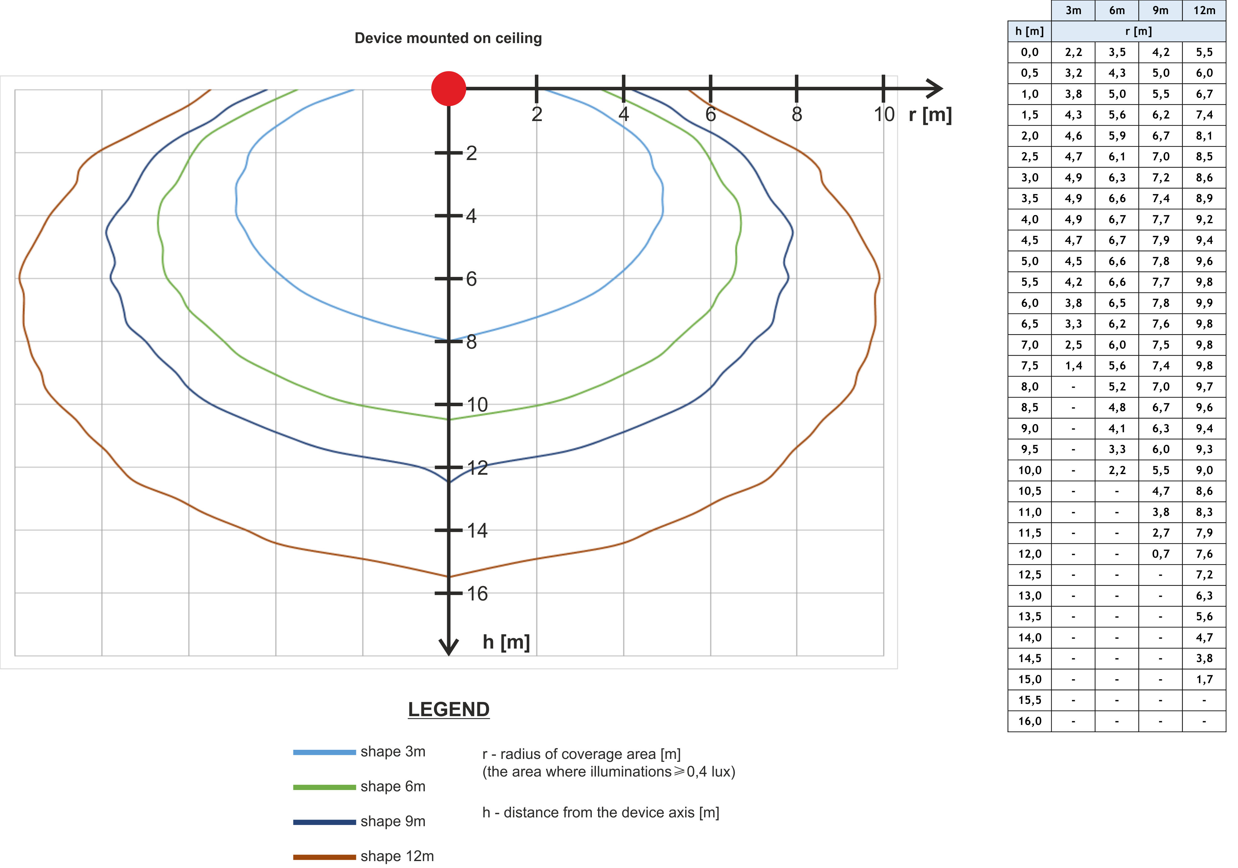
Ceiling mounting – white light:
The diagram for the installation of SO-P8 VAD (varieties with white light) on the ceiling is presented below. The table opposite shows the radius of the coverage area depending on the installation height (h) and selected optical shape.
Click to enlarge
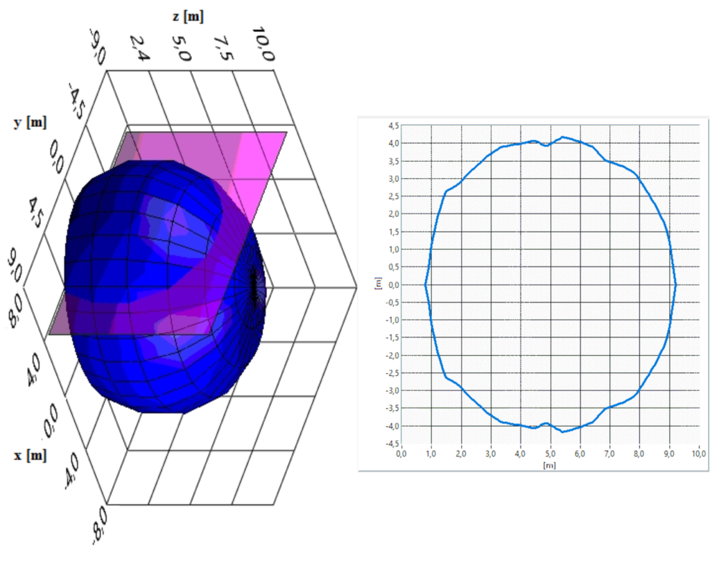
Wall mounting:
Photometric solids of the SO-P8 VAD – surface intensity >0.4 lx (cross-sections – parallel to the floor). Sections parallel to the floor with the signaling device hung on the wall, made at a distance x from the optical axis of the signaling device. Axes of all graphs scaled in meters. In the figure below, the SO-P8 VAD is mounted on the wall. At a distance (x=4m) from the axis of the signaling device, a cross-section of the photometric solid is presented, where the required lighting intensity is ensured.
Click to enlarge
In the drawing, the photometric solid is marked in blue, and the plane of the longitudinal section is marked in purple. In the example above, it is located at a distance of x=4 m from the optical axis of the signaling device (assuming that the signaling device is mounted at a height of 4 m and this height corresponds to the point x=0, y=0, z=0, then the figure on the right the longitudinal section corresponds to the area on the floor, where the illuminance is ≥ 0.4 lx (example for the SO-P8/CC signaling device, 6m solid).
In order to change the flash frequency of the signaling device, change the settings of the microswitches F0, F1 in accordance with the table below.
| Frequency |
Microswitch position |
| F0 |
F1 |
| 0,5 Hz |
ON |
ON |
| 0,93 Hz |
OFF |
ON |
| 1,12 Hz |
ON |
OFF |
| 1,3 Hz |
OFF |
OFF |
In order to change the optical shape of the signaling device, change the settings of the L0, L1 microswitches in accordance with the table below.
| Optical shape |
Microswitch position |
| L0 |
L1 |
| 3m |
ON |
ON |
| 6m |
OFF |
ON |
| 9m |
ON |
OFF |
| 12m |
OFF |
OFF |
In order to change the delay time between the VADs operating in the master mode and the next device operating in the slave mode, change the settings of the D0, D1, D2 microswitches in accordance with the table below.
| Microswitch |
Delay time
|
| D0 |
D1 |
D2 |
| OFF |
OFF |
OFF |
0 s |
| ON |
OFF |
OFF |
0,1 s |
| OFF |
ON |
OFF |
0,2 s |
| ON |
ON |
OFF |
0,3 s |
| OFF |
OFF |
ON |
0,4 s |
| ON |
OFF |
ON |
0,5 s |
| OFF |
ON |
ON |
0,6 s |
| ON |
ON |
ON |
0,7 s |